In the News – ONI Launches LNP PREP on Aplo Flow press release>
Aplo Scope
Last updated: February 18th 2026
Simple. Engineered. Dynamic. Powerful.
Aplo Scope is a compact, user-friendly super-resolution microscope from ONI, designed to enable high-quality single-molecule imaging with minimal setup and seamless integration into a wide range of research workflows.
Introduction
Print Section
Purpose
The Aplo Scope User Manual is a guide to the operations and maintenance of the device. This guide should be used as a reference for everyday use of the microscope.
Scope of this guide
This user manual will give guidance on the installation, operation and general maintenance.
Terms, abbreviations, and acronyms
| Word | Description |
|---|---|
| EV | Extracellular Vesicle |
| SBS | Society for Biomolecular Screening |
| HEPA | High Efficiency Particulate Filter |
| LED | Light Emitting Diode |
| AC | Alternating Current |
| USB | Universal Serial Bus |
General Instrument Safety
Print Section
The Aplo Scope is designed to be completely safe during proper use, but if equipment is used in a manner not specified by ONI, the protection provided by the equipment may be impaired. Incorrect use may result in personal injury or property damage. Please read these safety precautions and keep this manual for reference.
Disassembly
Disassembling the Microscope Module or Light Engine may result in malfunction, damage to the product, or injury. If you think disassembly may be necessary, please contact an ONI representative. Disassembly of the instrument from unauthorized personnel will result in a void warranty. Do not try to disconnect the Light Engine from the Microscope Module as both are attached to each other through the light link.
Laser safety
The Aplo Scope is a Class 1 laser product. Due to its inherent closed-form design, the interlock does not allow the lid to be opened without the lasers switching off. Do not attempt to modify the interlock in any way and attempt at doing so could expose users and people in the general area to class 4 lasers and may result in serious injury.
Contact with water
Avoid bringing water into contact with the product. If water is spilled on the Light Engine, turn off the power switches and remove the power cord. Wipe the liquid from the product. If water enters the Light Engine or Aplo Scope body at any point, please contact an ONI representative.
Stacking
Do not store any object on top of any part of the Aplo Scope.
Transportation
While the Aplo Scope and associated packaging is designed for portability, the complete Aplo Scope system weighs approximately 55 kg. Handle with care. Two persons are needed to lift the system.
Microscope stage
Do not place weight heavier than 200 g on the stage. Sample chambers / coverslips must be less than 97 mm long, 35 mm wide and 13 mm in height to avoid contact with the side of the lid, which might result in excess force on the stage and/or objective.
Safe handling of materials
The Aplo Scope is not designed to hold corrosive or radioactive substances. All legal regulations and local safety recommendations should be observed when handling hazardous substances.
Caution
Using the Aplo Scope by any method other than the procedures specified herein may result in hazardous radiation exposure.
Product Overview
Print Section
Intended use
The Aplo Scope is a high-performance super-resolution and live-cell imaging platform designed for advanced biological research. It enables precise visualization and quantification of single-molecule and subcellular structures across a range of applications.
Key Applications:
- Super-Resolution Microscopy (SMLM): Single-molecule localization imaging for high-precision spatial analysis.
- Live-Cell Imaging: Dynamic observation of cellular processes with minimal phototoxicity.
- Multicolor Imaging: Simultaneous detection of multiple targets for colocalization studies.
- Quantitative Imaging: Reliable measurement of molecular interactions, densities, and distributions.
- Automated Workflows: Streamlined acquisition with minimal user intervention.
Note
The Aplo Scope is intended for research use only (RUO) and is not for diagnostic or clinical applications.
Features
The Aplo platform revolutionizes the world of super-resolution microscopy through the combination of application specific kits and chemistry with fully automated fluidic control via Aplo Flow, class leading SMLM hardware with Aplo Scope, and innovative, user centric, and automated CODI software capable of delivering true end-to-end sample to answer experimentation of both fixed and dynamic molecular interactions.
Some key features include:
- Stable acquisition on any standard lab bench without an isolation table or dark room
- Large, homogenous 110 µm by 110 µm field of view
- Superb resolution of ≤15 nm
- Laser light engine with four discrete laser lines capable of consistent illumination from 0.01 kW/cm² to 3.325 kW/cm²
- Ten (10) expertly chosen emission filters in a turret wheel designed for rapid switching
- Advanced piezo stage driven in X, Y, and Z with 1 nm steps
- sCMOS Teledyne Prime BSI Express, with high quantum efficiency of 95% and high full well capacity
- Frame acquisition rate as high as 43 fps
- Class 1 laser safe device
- Class-leading minimal footprint of less than 95 cm² for both the Aplo Scope and gen2 light engine
Specifications
Print Section
Size requirements
The overall size of the Aplo Scope is:
- Width: 220 mm
- Depth: 420.5 mm
- Height (lid closed): 242 mm incl. feet
- Height (lid open): 406 mm incl. feet
The overall size of the Light Engine is:
- Width: 215 mm
- Depth: 420 mm
- Height: 457 mm incl. feet
Power requirements
The power requirements of the Aplo Scope system are:
- Input Voltage: 100 / 240 Volts AC
- Input Frequency: 50/60 Hertz
- Max. Power: 720W
- Max. Input Current: 7.2A @ 100VAC input
Installation requirements
The environmental conditions:
- Temperature: 18 – 30° Celsius or 64 – 86° Fahrenheit
- Humidity: 20% – 60% Relative Humidity
System and Facilities Requirements
Print Section
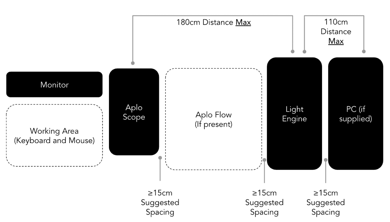
Space requirements
The Aplo Scope contains a Microscope Module and Light Engine which are permanently connected by the Light Link cord housing optical fibers, cooling, and electronic cables.
It is supplied with a PC to control the instrument. The cables include a USB-C cable to connect the Light Engine and the PC, the power cord for the Light Engine and the power supply for the PC.
Since the Light Link cord houses the optical fibers and the electronics cables, the Light Link should not be bent tighter than a radius of 75 mm. Due to heat dissipation, we also recommend 15 cm on each side of the computer free.

Environmental requirements
The Aplo Scope can be used on almost any platform, including a standard laboratory bench or a solid desk. It is critical that the following installation conditions are fulfilled:
- The Light Engine can only be used in the orientation shown above.
- Place the Light Engine on a clean, dust-free, and flat surface. Do not use it on a carpet.
- Keep objects and obstructions at least 15 cm from the air vents on the back of the Aplo Scope and Light Engine.
- Position the instrument in a manner that allows easy and convenient access.
- Avoid locations that are directly exposed to direct sunlight.
- Avoid installation locations which suffer from severe temperature fluctuations, particularly directly in or near the path of air handler vents.
- Avoid locations close to water sources (sink etc.).
Electrical requirements
Hazards
Fire Hazard – Improper fuses or high-voltage supply can damage the instrument wiring system and cause a fire. Before turning on the instrument, verify that the fuses are properly installed and that the instrument voltage matches the power supply in the laboratory.
Electrical Hazard – Grounding circuit continuity is vital for the safe operation of equipment. Never operate equipment with the grounding conductor disconnected. Use properly configured and approved line cords for the voltage supply in your facility.
Power Connectors
The Aplo Scope is shipped to customers with up to three power connectors. These connectors require standard 15A wall receptacles with proper grounding. Do not replace any mains supply cords with inadequately rated cords as this could become hazardous. Do not use extension cords.
The Aplo Scope can be used in any country with mains voltage from 100V to 240V, 50 to 60hz. The system is equipped with a universal power supply. In areas where the supplied power is subject to voltage fluctuations exceeding ±10% of the nominal value, a power line regulator may be required. High or low voltages can adversely affect the electronic components of the instrument.
Fuses
| Location | Type | Breaking Capacity | Rating & Speed |
|---|---|---|---|
| IEC mains plug (live) (UK & EU only) | Ceramic Cartridge Fuse, 6.3 x 25 mm | 6000A | 10A, 240Vₐ꜀, “F” |
| Power Inlet (live) | Ceramic Cartridge Fuse, 6.3 x 25 mm | 6000A | 10A, 240Vₐ꜀, “F” |
| Power Inlet (neutral) | Ceramic Cartridge Fuse, 6.3 x 25 mm | 6000A | 10A, 240Vₐ꜀, “F” |
| +24V Heater Supply | 0287005.PXCN Littelfuse ATOF blade, (not user replaceable) | 1000A | 5A, 32Vₐ꜀, “F” |
| Internal Power Supply (live & neutral) | HBC (not user replaceable) | unknown | 10A, 240Vₐ꜀, “F” |
System and Accessories Overview
Print Section
Package contents include:
| Part | Name | Description |
|---|---|---|
| 215-00007 | Desktop PC | PC for controlling Aplo Scope |
| 250-00073 | Monitor | PC monitor |
| 250-00072 | Keyboard and Mouse | Wireless keyboard and mouse |
| 135-00072 | Mousemat | ONI mousemat |
| 820-00147 | Magnets | Sample holding magnets |
| 600-00004 | Lens tissue | Lens tissue for cleaning objective lens |
| 820-00148 | Sample stage chip holder | Chip holder |
| N/A | Microscope power cable | Power cable for microscope |
| 150-00002 | TX6 screwdriver | Screwdriver for use with ONI stagetop incubator |
Packaging
The instrument will arrive in 1 box labelled ONI. The box is large and requires two people to handle. The box has been designed with lifting holes at each end.
The instrument will be accompanied by a desktop PC and monitor in separate boxes.
Images of the box Aplo Scope, closed (left) and open (right):
The scope and all the associated accessories will be packed in the boxes and will include the following items:
- Microscope
- Light Engine
- Desktop PC
- Light engine power cord
- Lens tissue
- Bead slide
- Magnets


Unboxing
Print Section
The installation and the setup of Aplo Scope will be completed by a trained ONI technician.
There are two layers to the packaging. The top ‘Accessory Layer” that holds the accessories + cables and the bottom layer containing the system itself.
Accessories
This layer contains items which should be unpacked and placed aside for use later during setup.
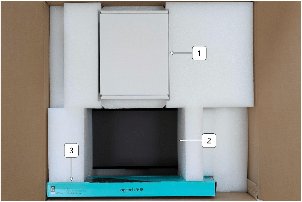
| ID | Item | Description |
|---|---|---|
| 1 | Accessories | Contains accessories such as power cables, tools, chip holder, magnets, and mousepad |
| 2 | Aplo Scope | Aplo Scope body is visible through the opening in top layer |
| 3 | Peripherals | Wireless keyboard and mouse combo |
Microscope and light engine
Once the top accessory layer has been removed, you will be able to access the system below to complete installation.

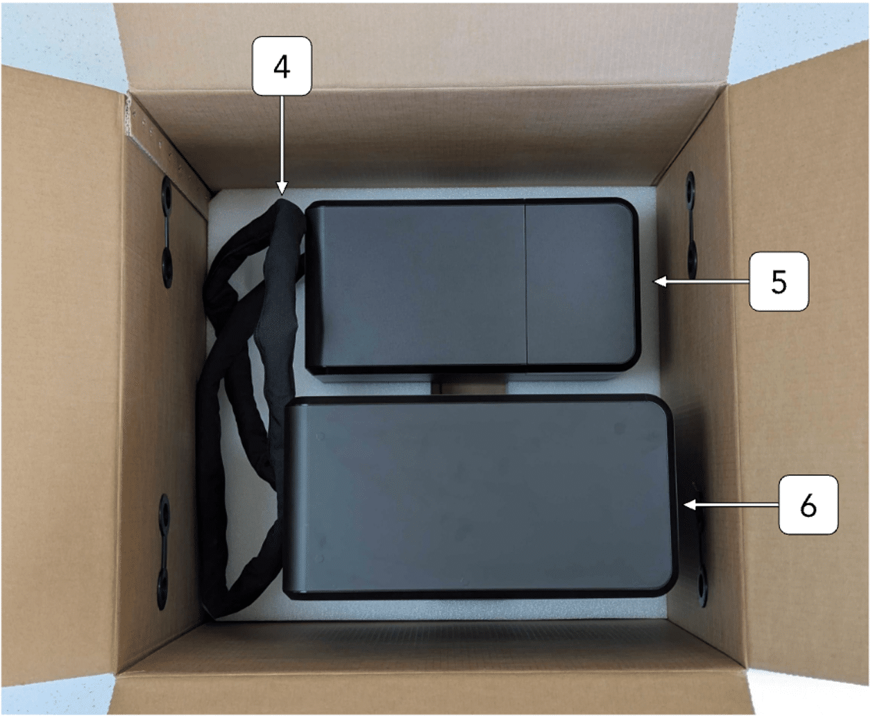
| ID | Item | Description |
|---|---|---|
| 4 | Light link | Protected connection between Aplo Scope and Light Engine |
| 5 | Aplo Scope | An all-enclosed microscope with an integrated camera, motorised stage, and autofocus for automated imaging |
| 6 | Light Engine | A built-in illumination system with automated brightness and wavelength control for optimal specimen lighting |
System Overview & Component Visualization
Print Section

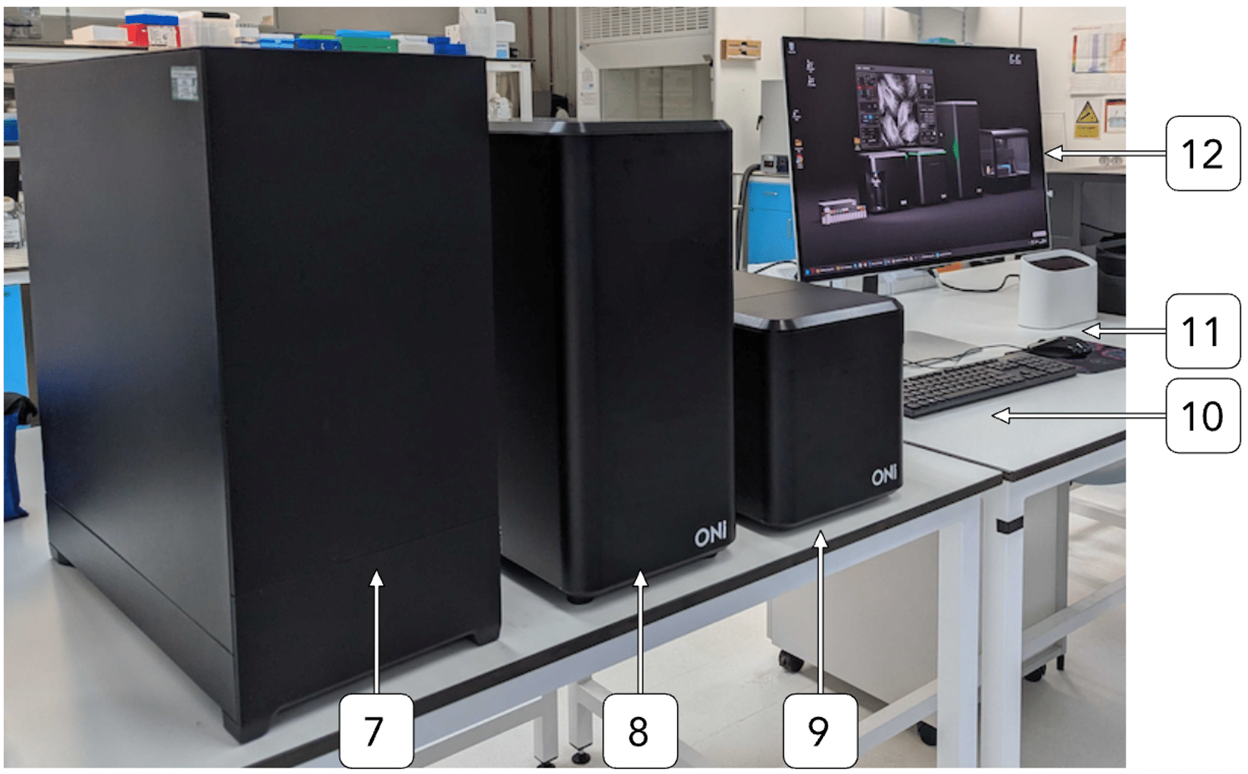
Product components overview
| ID | Item | Description |
|---|---|---|
| 7 | Desktop Computer | High-performance processing unit for microscope operation and image analysis |
| 8 | Light Engine | A built-in illumination system with automated brightness and wavelength control for optimal specimen lighting |
| 9 | Aplo Scope | An all-enclosed microscope with an integrated camera, motorised stage, and autofocus for automated imaging |
| 10 | Keyboard | Standard or specialized keyboard for data entry and system commands |
| 11 | Mouse | Pointing device for control and navigation |
| 12 | Monitor | High-resolution display for live imaging and software control |
Rear panel overview


| ID | Item | Description |
|---|---|---|
| 13 | Air vents | Air outlet with fan |
| 14 | Power inlet | Connects to the power adapter |
| 15 | Power switch | Powers the instrument on/off |
| 16 | Serial plate | Identification label for the instrument |
| 17 | USB cable | USB connection to a computer |
| 18 | Air vents | Air outlet |
| 19 | Light link | Includes optical fibres and electrical wires |
Internal features and parts
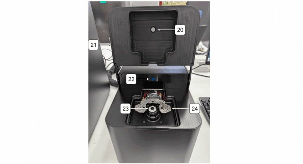

| ID | Item | Description | |||
|---|---|---|---|---|---|
| 20 | Transillumination LED | A light source located above the sample plate, providing brightfield lighting for specimens | |||
| 21 | Enclosure Lid | A protective cover that seals the microscope unit, ensuring dust-free operation and maintaining internal conditions | |||
| 22 | Push button | A simple control button for opening the back chamber of the microscope | |||
| 23 | Objective | A lens mounted on the microscope that provides varying magnifications for detailed observation of the sample | |||
| 24 | Sample plate | A flat surface where the specimen is placed for examination |
Installation
Print Section
Aplo Scope installation
The installation of the Aplo Scope should take approximately 2.5 hours. Removing the system from the packaging and setting up on the bench top will take 15-30 minutes. After the initial set up, a customer success engineer will run tests to verify that the system is working properly. These verification tests will take 1-2 hours to complete.
After the system has arrived at the facilities, the boxes should be moved to the site of the unpacking. If the installation is being done remotely, we recommend that 2 people from the lab are present to remove the system from the packaging. The following are the steps that should be followed for unpacking and installation of the scope:
-
- Cut the tape to gain access to the box, care should be taken when performing this action.
- Remove the foam around the Light Link. As this is done, verify the connection points to the Light Engine and scope are visible. The image below shows the Aplo Scope with the excess foam removed.
- Two people should carefully place the Light Engine and the Aplo Scope on the bench top. Continue to ensure there is not a strained or tight bend on the Light Link. Ensure the light engine is on the left-hand side of the Aplo Scope.
- Remove any remaining foam to reveal the other components located in the box. These components include:
- Light Engine power cable
- Bead slide
- Lens cleaning tissue
- Magnets
- Torx 6 screwdriver
- Sample stage chip holder
- Mouse and keyboard
- Mousemat
- Connect the desktop PC power supply into the wall outlet.
- Connect the Light Engine power cord to the back of the Light Engine and the other end of the power cord to the wall outlet.
- The next portion of these instructions will involve handling the objective lens and sample stage. If not done already, please put on gloves and proceed with caution.
- Lift up the front lid to check the sample stage.
- Begin the process of removing the stage stabiliser (image below).
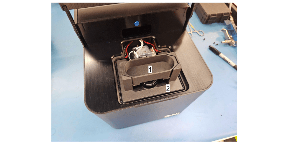
- Lift the internal hollow part (1) of the stage stabilizer carefully to remove it (image below).
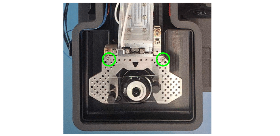
- Using the provided TX6 screwdriver, remove the 2 screws holding the sample plate to the stages, taking care not to drop them into the system.
- Once the sample plate is fully loose, lift it out of the system and place to the side with the screws.
- Remove the lower part (2) of the stage stabiliser from the system.
- Both parts of the stage stabiliser can be stored to one side as they will be used in the case that the system needs to be transported.
- Refit the sample plate using the screws that were previously removed. These screws should be tightened so that they are finger tight, without applying excessive torque.
- Close the front lid.
- Turn on the Light Engine by toggling the switch to the “I” position on the back.
- Turn on the desktop PC. When prompted to log in, use the Windows credentials provided for the system during the installation process.
Operation
Print Section
LED color indication
The front of the Aplo Scope system has a LED indicator that will illuminate solid blue to indicate the machine is powered on.
Microscope operation
See the ONI Aplo Scope Control User Guide for detailed instructions and information on operation of the Aplo Scope software and interface.
Control Software
Print Section
The Aplo Scope Control: User Guide is a reference for everyday use of the control software for Aplo Scope. The CODI System App (CSA) operates in the background to connect the Aplo Scope and light engine to CODI. Aplo Scope requires this connection to be active to operate. Further information about CODI can be found at the CODI Help Center.
Aplo Scope Requirements
Aplo Scope Control and the CSA are designed to function with the PC provided with Aplo Scope. The interface is designed for high resolution monitors (2560×1440 or larger, if possible).
Aplo Scope Control and CODI require an active internet connection, and require a CODI account provisioned by ONI for access to Aplo Scope Control.
Terms, abbreviations and acronyms
| Term | Description |
|---|---|
| CODI | COllaborative DIscovery |
| CSA | CODI System App |
| FOV | Field of View |
| LUT | Lookup Table |
| HW | Hardware |
| MAS | Multi-Acquisition Sequence |
| PAINT | Point Accumulation for Imaging in Nanoscale Topography (a type of SMLM) |
| PALM | Photo-Activated Localization Microscopy (a type of SMLM) |
| ROI | Region of Interest |
| SMLM | Single-Molecule Localization Microscopy |
| SNR | Single to Noise Ratio |
| SPT | Single Particle Tracking (a type of SMLM) |
| STORM | STochastic Optical Reconstruction Microscopy (a type of SMLM) |
Installation & Updates
Login to CODI
Aplo Scope Control requires a CODI account. To sign up, navigate to https://alto.codi.bio/, click the Sign up link, or use the Login with Google function. Once the account is created, it must be provisioned for access to Apo Scope Control. Contact ONI for more information.
Installing CODI System App
Navigate to https://alto.codi.bio/ to open CODI. Open the Acquisition Apps tab, then click on the Aplo Scope Control App.

When first installing the CSA, allow access if any Windows Security Alert appear to ensure that Aplo Scope functions correctly.

Periodically Aplo Scope Control will be improved with new updates, prompting the user to download a new version of the CODI System App (CSA). When prompted, click Download Now to install the latest version of CSA. Ensure the current CSA is closed prior to installation
Getting Started
Launching CSA
Once the latest version of the CSA is installed, open it and wait for the status indicator to change from Initializing to Running. This generally takes 1-3 minutes.
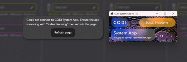
While CSA is initializing, a popup appears in the CODI webpage. Click Refresh Page once the status is Running to connect CODI to Aplo Scope.
In the uncommon event where a connection is not established, double-check that no other CODI webpages are open in any other browsers or tabs, and use the browser refresh button to reload the page.
Setting a default Aplo Scope temperature

When CSA is launched, it automatically begins heating the Aplo Scope. In the top right corner of the CODI webpage, click on the temperature icon with a blue background and outline of a thermometer to navigate to the System Info page. Over time, this is continually updated with new telemetry for the Aplo Scope.
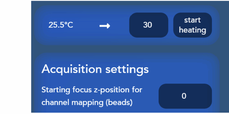
It typically takes up to 2 hours for the system to reach thermal equilibrium, which is important to minimize sample drift. For SMLM, it is recommended to heat the system to 31°C by entering the 31 in the textbox and clicking Start Heating, while for live-cell imaging an equilibrated temperature of 37°C should be used. Diffraction-limited imaging of fixed cells can be performed at any temperature and does not require system equilibration. Once heating has been stated, the temperature on the left (current system temperature) rises until it meets the desired temperature.
Note
Temperature setpoint is saved as the default temperature for the next time the CSA launches.
Launching Aplo Scope Control
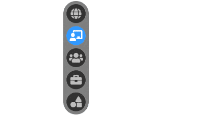
With the CSA open and Ready, navigate to https://alto.codi.bio/ and open the Acquisition Apps tab on the left pane. Click on Aplo Scope Control.
Aplo Scope Control
The CSA should be displaying Running prior to opening the Aplo Scope Control App to ensure that the Aplo Scope communicates properly with CODI.
Aplo Scope Control is designed to put the Aplo Scope large field of view front and center, while having quick and intuitive access to all the required controls without complex menus.

Instrument settings and hardware (HW) control for the focus, stage, illumination, and camera line the left side of the app.
The right side contains controls for visualization, as well as options to configure the acquisition type and data options.
The next sections dive deeper into the details of each section.
Experiment settings
CODI creates a new experiment each time Aplo Scope Control is opened, which groups together information about all of the acquisitions performed during a given session.
The Experiment Settings widget allows users to modify experiment metadata, such as name and tags, and load settings for the experiment contained in Workspaces (described below).

Control | Description | |
|---|---|---|
| Experiment name | (Optional) Add metadata in the form of tags to all the datasets acquired during the acquisition. This makes organizing and finding these datasets in CODIs cloud analysis platform easier. Click the pencil icon to edit. |
| Tags | (Optional) Add metadata in the form of tags to all the datasets acquired during the acquisition. This makes organizing and finding these datasets in CODIs cloud analysis platform easier. Click the pencil icon to edit. |
| Data save location | Aplo Scope Control saves data locally in the C:/Data/CODI/ folder. It is currently not possible to change this location. Each time a new Aplo Scope Control tab is opened, a new experiment is created, and a new folder is created corresponding to this experiment, using the structure: exp-YYYYMMDD-experiment_id-experiment_name – Where, YYYY is the year, i.e. 2025; MM is the month, i.e. 04; and DD is the day, i.e. 16. – experiment_id is a unique identifier for the experiment, created by CODI and not user-modifiable, i.e. zaz3jh0wwq – experiment_name is the name of the experiment given by the user in the Experiment Name textbox. |

Workspaces
Workspaces allow the customization of the Aplo Scope Control app to a specific kind of experiment, by saving all the settings to quickly set up the experiment:
- Illumination channels, including custom names, lasers and filter combinations
- Camera exposure time
- Multi-acquisition sequence channels

Workspaces are a great way to configure Aplo Scope Control experiments that are run frequently and easily swap between different settings or configurations.
Select a workspace by clicking on the Workspaces dropdown menu, which displays a list of all available ONI-provided and custom workspaces.
The Default Workspace is currently the only ONI-provided workspace, and it contains a standard illumination channel list, where each laser line is configured to use the most appropriate single-band filter. This workspace can be customized, but changes must be saved into a new workspace. The next time Aplo Scope Control is opened, it reverts to the default workspace settings. In the future, more ONI Default workspaces will be provided to help getting started with the ONI Application kits.
To create a new custom workspace, click on the Save as new workspace button next to the workspace dropdown menu and enter the desired workspace name.

When a workspace has been modified, the settings button in Workspace Setup turns yellow to designate an unsaved modification to the workspace.
- To save changes to the workspace, click on the Workspace Setup button and click Save Workspace. This updates the current workspace with any new settings, like channel names or sequence steps.
- To revert back to the original workspace settings, click the Revert button on the far right. This allows quick access to returning to saved workspace values
Workspaces can be renamed by changing the name of the workspace in the Workspace Setup. Workspaces can be deleted by clicking on the Delete button in the Workspace Setup and confirming deletion.

Workspaces are saved to the CODI user account and can be accessed from any Aplo Scope. They cannot be shared between users at this time.
Focus control

The first step to any microscopy experiment is to find focus. Aplo Scope uses a precise piezoelectric stage to control movement of the sample in x, y, and z. To focus, the stage is moved in the z (axial) direction, while the microscope objective remains fixed.

The Aplo Scope is calibrated out of the factory such that an ONI bead slides focus is around Z=0 µm. Typical focus values for other conventional slide types can be found here:
Slide Type | Typical Focus |
|---|---|
| ONI bead slide (coverslip mounted under 35 mm slide) | 0 µm |
| ONI 4-lane assay chip | -250 µm |
| Ibidi 8-well slide | -300 µm |
Since finding the initial focus of the slide surface can sometimes be tricky, Aplo Scope Control makes it easy to find a general focal plane near the coverglass and then refine focus to the desired imaging surface in just three simple steps:
- Find the coarse focus of the coverglass (manually or using Scan for Surfaces)
- Manually optimize the z position to find the imaging surface
- Calibrate and engage the focus lock, so the focal plane is retained over time and while moving the sample in XY.
Find the coverglass quickly with Scan for Surfaces
Scan for Surfaces automatically detects any potential imaging surfaces on the slide mounted to the Aplo Scope. See the section below for manual coarse focusing.
To use Scan for Surfaces:
- Click Scan for Surfaces
- When complete, enable a laser to visualize the fluorescence signal from the sample during the scan for surfaces (see Enabling a Channel).
- Select a surface by clicking the next/previous surface button, or clicking on an identified surface, displayed as ● in the surface identifier.
Note
It is common to detect more than one surface and for the detected surface to be slightly out of focus (within a few micrometers). The goal of Scan for Surfaces is to identify the coarse focus position. In the next step, the focus is refined to the optimal focus for SMLM or live cell imaging.
Control | Description | |
|---|---|---|
| Scan for Surfaces | Clicking runs an automated scan to attempt to identify any optical surfaces between z= [-500 µm to +500 µm]. This uses a dedicated IR laser and focus camera to detect strong differences in refractive index, indicating the potential for an imaging surface, like the top of the coverglass. When complete, the number of identified surfaces is displayed and the next/previous surface buttons are enabled. |
| Next/ Previous Surface | Quickly jump between detected surfaces. |

| Surface Identifier | The surface identifier displays the detected surfaces in a visual format to help relate the current stage position to the detected surfaces. Click on any detected surface to immediately move the stage to this focus position. ● The current focus position ● A potential surface, detected by Scan for Surfaces ● The selected surface (either by clicking or using next/previous surface buttons) |


Focus manually
The coverglass surface can alternatively be found by focusing manually in several ways:
- Clicking the z up/down button (hold Shift to move 5x step size)
- Using the W/S keys (use Q/A to move 5x step size)
- Typing a value into the z position input, in microns (µm).
The coverglass surface positions roughly the same for similar sample types. For example, ONI 4-lane assay chips will all have roughly the same focus position, whereas an Ibidi 8-well slide will be different. This is largely due to the way the slides and coverglass are mounted, and how that ensemble is mounted onto the stage.
Optimize focus using a fluorescence signal

Once the coarse focus has been achieved (either manually or using Scan for Surfaces), ensure a laser is enabled (corresponding to a channel where fluorescence signal is expected) and manually refine the focus using the z up/down button, or the W/S arrow keys (up/down).
For beads or particles adhered to the surface, the optimal focus position is where the signal is brightest and the point spread functions are the smallest, as seen below.

(Recommended) Activate focus lock
The focus lock ensures that the focal plane remains constant, compensating for slight changes in temperature or small slants of the mounted slide.
It is strongly recommended to activate focus lock while using Aplo Scope by:
- Finding the desired focus position to lock on to
- Clicking the Calibrate button to calibrate the focus lock
- Clicking the Lock icon to engage the focus lock
Note
The focus lock remains engaged when opening the lid of the Aplo Scope. Make sure to manually deactivate it prior to opening the lid.
Here are the different focus lock controls and how to use them:
Control | Description | |
|---|---|---|
Calibrate (Re-calibrate) | The focus lock calibration is required before activating z-lock. The calibration process sweeps the stage in the z-direction ± 20 µm around the current focal plane, while detecting an infrared lasers reflection off the surface using a dedicated focus camera. This calibration process takes ~5-10 seconds. The calibration is extremely sensitive to immersion oil and the glass slides, and should be re-calibrated each time a slide or chip is placed on the Aplo Scope. | |
| Engage focus lock (shown when z-lock is disengaged) | Engage the focus lock. When focus lock is engaged, the system continuously monitors the infrared lasers reflection off the coverslip surface and compares it to the reference stack created during calibration to make small changes to the z position of the stage to retain the same focus. If this is clicked and immediately deactivates, try re-calibrating the z-lock, as the calibration may no longer be valid. |
| Disengage focus lock (shown when z-lock is engaged) | Disengage the focus lock. While disengaged, the infrared laser remains on, but the system is not monitoring changes. Ensure to disengage the z-lock before removing a slide from the Aplo Scope. |
| Offset up/down | When the z-lock is engaged, adjustments to the focus are made by adjusting the offset relative to the z position where the focus lock was engaged. This z-lock offset is relative to the focus position where the z-lock was engaged, and helps maintain a reference in 3D space when trying to focus the sample. The default offset step size is 0.1 µm, ensuring that when z-lock is engaged, precise adjustments to focus are possible. |


Focus: z vs. offset position
| Control | Unit | Description |
|---|---|---|
| z | µm | The absolute axial position of the stage. |
| Offset | µm | The axial position of the stage relative to where the z-lock was calibrated. |
Focus: Typical focus positions
The Aplo Scope has been aligned out of the factory to normalize the focus position of the ONI bead slide. Listed below are the rough focus positions of typical slide types.
| Slide Type | z position for focus (µm) |
|---|---|
| ONI bead slide | 0 µm |
| ONI 4-lane assay chip | -250 µm |
| Ibidi 8-well slide | -250 µm |
Z-step size settings

Click the settings icon in the top right corner of the focus control widget to open the settings drawer, containing the ability to set the step size when using the step buttons or the keyboard controls. Quick default settings are adjacent to the step size input for quickly jumping between fine or coarse focus controls.

| Control | Description |
|---|---|
| z-step | The displacement of the stage in the z-direction when clicking the up/down z buttons, or using the W (up) or S (down) keys. |
| Offset-step | The displacement of the stage in the z-direction when focus lock (z-lock) is engaged when clicking the up/down z buttons, or using the W (up) or S (down) keys. |
Stage control
The Aplo Scope uses the same piezoelectric stage for lateral and axial displacement of the slide, providing very fast and precise sample control in 3-dimensions.
| Control | Description |
|---|---|
| Move the stage in the desired direction, or use the up/down/left/right arrow keys. Hold Shift to 5x the step size. |
| Indicates the current position of the stage in x,y. Hover and click to manually enter a value. |


XY step size settings
Click the settings icon in the top right corner of the Stage Control widget to open the settings drawer, containing the ability to set the step size when using the buttons or the keyboard controls. Quick default settings are adjacent to the step size input for quickly jumping between fine or coarse focus controls.
| Control | Description |
|---|---|
| XY-Step | The displacement of the stage in the xy-direction when clicking the stage movement controls or using the arrow keys |
| Set the step size to exactly the size of the field of view (~110 µm x 110 µm) |
| Use the xy-step size input to displace the stage by a fixed step size in µm. |

| Reset the stage position to (0,0) |


Controlling the stage and focus with the keyboard: summary
Aplo Scope Control gives the option to control the focus (z) and stage (x,y) using the keyboard.

| Key | Stage movement |
|---|---|
| W | +z by step size |
| S | -z by step size |
| Q | +z by 5x step size |
| A | -z by 5x step size |
| Up Arrow | +y by step size |
| Down Arrow | -y by step size |
| Left Arrow | -x by step size |
| Right Arrow | +x by step size |
| Shift | Use in conjunction with any above key to increase step size 5x |
| Alt/Option | Use in conjunction with any above key to reduce step size 5x |
Illumination Control
The bottom left widget contains the controls to manipulate the illumination and detection of the Aplo Scope, including controls for lasers, filters, illumination angle and camera settings.

Illumination control contains several groups of controls stacked linearly for easy access:
- Laser power display: quickly see which lasers are active and at which % power.
- Laser and transillumination controls: quickly enable/disable and finely tune illumination on the sample.
- Filter controls: easily select any emission filter
- Illumination angle: finely tune the illumination angle to move from epifluorescence through HILO to TIRF illumination.
- Exposure control: quickly set the camera exposure time to match the sample.
More detail of each control is outlined below:
Control | Description | |
|---|---|---|
| Lasers illumination channels | The Aplo Scope comes equipped with 4 lasers with very high dynamic range, allowing low-power live-cell experiments as well as high-power SMLM experiments. Laser channels allow for quick control and swapping between different fluorescence channels.
|
| Brightfield illumination channel | The transillumination array in Aplo Scope can be used to obtain brightfield images. Brightfield channels are treated like special laser channels, and can be used anywhere laser channels are, for example, a brightfield channel can be inserted in any multi-acquisition sequence to give cellular context to the fluorescence channels.
|
| Emission filter | Any of the Aplo Scopes emission filters can be selected from the list to manually change the emission filter and observe the fluorescence in that specific channel. The 2 modes of operation of the filter wheel, automatic and fixed, are detailed in Filter Wheel Control.
|
| Illumination angle | Aplo Scope provides the ability to adjust the illumination angle across a wide range of angles. This angle is controlled by changing the position where the laser enters the objective. The Aplo Scope has been calibrated out of the factory to allow fine-tuned control of the output angle of the lasers. 0°: Epifluorescence ~65°: Total Internal Reflection Fluorescence (TIRF) angle Note: The optimal TIRF angle varies depending on wavelength, and each multi-acquisition sequence step can have a dedicated illumination angle depending on the desired imaging (See Multi-acquisition sequence – channel sequence for more details)
|
| Exposure time | Set the camera exposure time. Note: There is currently a lower limit of 30 ms/frame. This will decrease in the near future. Additionally, the frame rate is currently always 1/(Exposure Time). The option to independently control the exposure time and frame rate will also be added in the future.
|


What is an Illumination channel
An illumination channel is a control mechanism that facilitates accurate observation on the Aplo Scope by automatically selecting the appropriate emission filter corresponding to the active excitation laser. By creating or editing channels that map to the samples fluorescence and targets, illumination channels direct user attention to the sample instead of to the Aplo Scopes settings (see Channel Setup – Adding a Channel for more details).
Enabling a channel – turning on a laser or brightfield
Click on the icon or the channel name to toggle the Illumination Channel on or off.

Illumination channels provide power control in 2 ways:
- Using a slider to make coarse adjustments to the power. Note the non-linear scale makes it easy to control low power doses while also accessing high power ranges.
- Using the Text Input to set precise values or make fine-tuned adjustments
Note: The laser power indicated at the far right of the illumination channel is the laser power emitted by the light engine, and is not representative of the power experienced at the sample plane.


If the filter control is set to automatic filter mode, the filter automatically switches to the specified filter for this illumination channel. When the system controls this switching without user intervention, it highlights the filter selection dropdown in blue for several seconds. See filter wheel control for more information.
Default single-band filters for each laser illumination [default workspace]
The default workspace automatically selects the most commonly appropriate single-band filter for each laser channel.
The associated filter for each channel can be modified by entering Channel setup.
Note: The default filter for the brightfield channel is the quad-band filter. If the intensity of the brightfield image saturates the camera, select the neutral density filter from the list.
Channel Setup
Channels can be added, modified, or hidden using the Channel setup button in the top-right of the illumination channel widget.
Channel setup – adding a channel
Clicking the + Add Channel button opens an Add New Channel panel.

State | Action | |
|---|---|---|
| Name | The channel name is its main identifier. It will be displayed in the illumination list and the multi-acquisition sequence. Note: Giving semantic names, e.g., the name of the biological structure, simplifies viewing and organizing data and analysis in CODI as the channel names carry through to datasets in the cloud. |
| Fluorophore | (Optional) Selecting a fluorophore from the list automatically selects the best combination of laser and emission filter for Aplo Scope. Note: The laser and filter can always be changed. Once a channel has been assigned a fluorophore, the fluorophore can be changed, but it cannot be removed. To do so, create a new illumination channel with no fluorophore. |
| Laser | Select one or more lasers controlled by the illumination channel. |
| Filter | Select an emission filter to be used for the channel. |


Click Save Channels to save the changes to the illumination channel, or click Cancel to reject any ongoing changes.
Channel setup – editing a channel

Any individual illumination channel can be modified by clicking the pencil icon. Once finished modifying its name, fluorophore, laser, or filter, click Save Edit to save the changes to the illumination channel, or click Cancel to reject any ongoing changes.
Channel setup – editing/showing a channel
The illumination channel list can be customized to hide infrequently-used illuminations. For example, if the brightfield is not used frequently, it can be hidden from display to allow the user to focus on their fluorescence channels.

Channels can be hidden from the illumination list by clicking the hide/shown button while in Channel Setup.
State | Action | |
|---|---|---|
| Visible | Click to hide |
| Hidden | Click to hide |


Channel setup – deleting a channel
An illumination channel can be completely deleted from the workspace by editing the illumination channel, clicking Delete, and confirming deletion. This can be helpful to clean up a workspace with many illumination channels.
Filter Wheel Control
Aplo Scope contains a wide range of emission filters to precisely control the detection on its sensitive camera. Four different types of filters are included: Single Band, Dual Band, Quad Band, and Neutral Density.

Filter name | Type | Center wavelength | Bandwidth |
|---|---|---|---|
Blue | Single Band | 445 nm | 30 nm |
Green | Single Band | 527 nm | 49 nm |
Orange | Single Band | 595 nm | 44 nm |
Orange-Red | Single Band | 615 nm | 40 nm |
Red | Single Band | 673 nm | 35 nm |
Far-Red | Single Band | 760 nm | 110 nm |
Green Orange | Dual Band | 519 nm 605 nm | 35 nm / 35 nm |
Green Red | Dual Band | 519 nm 673 nm | 35 nm / 35 nm |
Orange Red | Dual Band | 605 nm 673 nm | 35 nm / 35 nm |
Quad Band | Quad Band | 446 nm 515 nm 597 nm 673 nm | 16 nm / 25 nm / 25 nm / 35 nm |
ND5 | Neutral Density OD5 |
For multi-band filters with several pass-bands, each pass-band is described by its center wavelength and its bandwidth, as shown in the following figure.

Aplo Scope Control denotes multi-band filters by using the symbol to join center wavelengths of the pass bands. For example, the Orange Red multi-band filter has 2 pass-bands; the first of which has center wavelengths of 605 nm, and the second at 673 nm. The bandwidths of each pass-band can be found in the above table.
There are 2 modes of operation of the filter wheel:

Auto mode (default)
The emission filter switches automatically to the active illuminations designated filter. This makes it easy to use the Aplo Scope without having to consider which filter is optimal.

Fixed mode
The emission filter remains on the selected filter, regardless of the active illumination channels designated filter. This makes it easy to manually control the filter and evaluate the sample with any filter. If a filter is selected from the list manually, the filter switches to Fixed operation until manually switched back to Auto mode.
Camera Viewer

The camera viewer is central in Aplo Scope Control and is the main display into the sample.
Zoom in or out by hovering over the display and using the mouses scrollwheel. A scale bar in the bottom left corner scales dynamically as the zoom changes. The scale bar can be dragged anywhere in the camera viewer to measure objects in the sample.
Additional zoom options are available using the action bar.
Camera visualization options

The Camera Visualizations Options widget is composed of 2 sections:
- Brightness and contrast adjustment
- Camera stream layer options
Auto scale vs. manual intensity scaling
The camera signal intensity can be displayed with auto scaling or with manual scaling, which allows full control over the visualization of the sample.
| Control | Description | |
|---|---|---|
| Activate Manual Intensity Scaling (currently in Auto Scaling) | When in Auto Scale mode, the brightness and contrast of the camera stream is adjusted in real-time to enhance visibility of the samples signal. It does not alter the actual data coming off the camera, but is simply changing the dynamic range of what is being displayed. The Auto Scale behavior can be fine-tuned using the sliders. These sliders set the intensity percentiles that define what appears as pure black and pure white in the image. For example, if the black point is set to the 1% percentile, the darkest 1% of pixels appears completely black, helping to optimize contrast. |
| Activate Auto Scaling (currently in Manual Intensity Scaling) | When in Manual Intensity Scaling mode, the brightness and contrast of the camera stream are fixed, specified by the slider values in ADU (16-bit). This mode is especially useful when trying to quantitatively assess the sample, such as comparing signals across channels or filters. |


Changing camera LUT
Aplo Scope Control defaults all channels to grayscale accessibility and simplicity.
To visualize the camera stream using a different lookup table, click the gray gradient on the right side of the Camera Stream channel button and select from a list of available lookup tables.
A few of ONIs favorite LUTs for the camera stream are:
- Blue-Magenta-Yellow most closely resembles the Fire LUT from ImageJ
- Rainbow is a great pseudocolor LUT for visualizing small changes in intensity
Live Localization Viewer

The live localizations viewer opens any time an acquisition containing an SMLM channel is run, and displays a preview of the localizations accumulated during that acquisition to aid understanding the state of the single molecule imaging process.
Localizations remain in this view until they are cleared by starting a new acquisition.
Note: The live localizations viewer displays a raw preview of all the localizations, they are not processed, filtered or drift corrected.
Live localization visualization options
All of CODIs localization visualization options are present in Aplo Scope Control. This widget is separated into 2 sections:
- Camera and localization options
- Per-channel adjustments
Camera options
Click the set camera to manually set the camera viewport options, such as xy-position and zoom factor.
Image outline on/off
Click Outline Hidden to toggle between a visible border surrounding the data in the camera stream and localization images. This helps contextualize the sample with respect to the camera frame.

Localization brightness and auto scaling
Similarly to the camera view (See Auto scale vs. manual intensity scaling), Aplo Scope Control provides the ability to adjust the brightness of the localizations in the preview.
- When the toggle is set to auto (percentile) the value of the slider refers to a threshold on the intensity distribution of the pixels in the image. Every pixel that has an intensity value higher than this threshold is saturated to the maximum intensity value of the screen. For example, if the threshold is 90, then the pixels in the top 10% of the intensities in the current view are saturated to the maximum brightness. If the threshold is lowered then more pixels in the view are saturated and therefore the image appears brighter.
- When the toggle is set to manual, the intensity values of the localizations are set to the maximum pixel value that the screen can display divided by the value selected on the slider. Therefore setting the raw threshold lower increases the brightness of the image. For example if the value is set to 2, all of the localizations in the view will have the intensity of the maximum pixel divided by 2.
Fixed vs. precision localization rendering
Localizations in the preview can be rendered in 2 different manners: fixed or precision.
- When the toggle is set to fixed, every localization has the same size and the slider allows the user to change that size. In this mode the slider determines the standard deviation of the Gaussian used to render that localization. In fixed mode, every localization appears the same size.
- When the toggle is set to precis. (precision), the size and intensity of localization is dependent on how precisely it was localized. Small and bright are good localizations while large and dim are poorer quality localizations, i.e., the standard deviation of the Gaussian is set to the precision of the localization.
Per-channel options
- Toggle Selection on/off: Clicking on the channel name selects/deselects the channel for adjustments with the sliders. A channel is selected if it is outlined in its LUT color.
- Toggle on/off: Hides or shows the localizations from that entire channel in the preview. This can be helpful to quickly assess the relative organization of several markers.
- LUT: Like the camera stream, each localization channels LUT can be adjusted. By default, the channels use the LUT from their respective sequence step (See Multi-acquisition sequence for more information about sequence steps).
Action bar
The action bar is a toolbar that provides quick access to frequently-used actions. Currently, the action bar contains options for controlling the way data is displayed, including showing/hiding viewers and zooming in and out.

Control | Description | |
|---|---|---|
| Show/Hide Camera Viewer | Toggle the display of the live camera viewer. Note: Hiding this view does not stop the camera, it only hides the view of the camera stream. The camera continues to operate even when hidden.
|
| Show/Hide Live Localizations Viewer | Toggle the display of the live localizations viewer. Note: When starting a multi-acquisition sequence with an SMLM channel, this preview viewer automatically opens.
|
| Zoom In/Out | This allows users to zoom in and out on the display. Zooming in and out can also be done using the mouse wheel or trackpad gesture (up/down). Note: The camera viewer and live localization viewer are synchronized in their zoom and position, panning and zooming one moves the other.
|
| Zoom to fit | Reset to the default zoom and position so that the entire FOV fits inside the camera viewer. |


Multi-Acquisition Sequence
The multi-acquisition sequence widget is the primary component that allows the configuration of simple or advanced acquisitions.
The tab bar in the multi-acquisition sequence widget reveals settings for different standard modes of acquisition, from multi-channel sequences, to timelapse and FOV tiling.

Important
Only the channel sequence tab is currently functional, the other tabs will be enabled in future updates.
Multi-acquisition sequence – channel sequence
The channel sequence allows configuring of single-channel or sequential multi-channel acquisitions, typical in SMLM experiments.
These sequences are acquired sequentially from top to bottom, and each step of the sequence is considered a distinct channel in the generated datasets.
Important
At least one step in the channel sequence must be added before data can be acquired.
Multi-acquisition sequence – adding a step

There are 2 ways to create a step in this sequence:
- Add active illumination: Adds a step using the currently enabled illumination channel (laser and filter), as well as any other specifics to the instrument state (laser power, TIRF angle, exposure time, and z-offset if z-lock is engaged). Once added, the number of frames desired for that step must be entered (for SMLM acquisitions, several thousand frames is typical).Adding active illumination is convenient when tweaking imaging settings to find the perfect laser power and TIRF angle right for this step in the sequence.
- Select channel from list: Prompts to select one or more channels from a list of the illumination channels, as well as the channel type (diffraction-limited (DL) snapshot (SNAP) vs. SMLM), number of frames and laser power to use.This is very convenient when adding multiple steps with similar state, for example when quickly assessing staining across different channels.
Once a step is added, it displays as a row in the table, displaying all of the important context of the step, in order to add confidence that the acquisition runs as expected.
Continue to add as many steps as necessary for the desired acquisition. If uploaded to CODI, all of the channels are merged into a single dataset, and each step is a distinct layer in the CODI dataset.
Once added, any of the steps settings can be modified. See multi-acquisition step – editing or removing a step for more details, and the table below for detailed description of each setting.

Control | Description | |
|---|---|---|
| Channel LUT | The coloring of this channel as it displays in the live localizations view. This cannot be currently modified. |
Channel name | The name of the channel, inherited from the illumination channel step. This channel appears with this name in the dataset, so make sure to create memorable and unique names for each channel. | |
| Channel type | Channel type refers to specifics about how to acquire and post-process each step of the sequence. |
| SMLM Channels | SMLM Channels (default) are acquired and localized. Results from SMLM channels appear in the live localizations view and the point cloud. |
| SNAP Channels | SNAP Channels are acquired and processed as diffraction-limited data. Results from SNAP channels do not appear in the live localizations view, but in CODI as a single averaged image. |
| Number of frames | The number of imaging frames to acquire for that step. See Number of frames – recommendations for more info. |
| Illumination/laser type | Choose the illumination being used for that step. For laser illumination channels, any single laser can be selected. To set up a channel with multiple lasers, create a new channel. For brightfield channels, the transillumination array is the only option. |
| Illumination/laser power | Set an illumination power |
| Emission filter | Choose the emission filter |
| Exposure time | Set the exposure time. Note it is possible to have different exposure times for each channel, to optimize the collection efficiency from different fluorophores |
| Illumination angle | Set the illumination angle. Note it is possible to have different illumination angles for each channel, allowing customization of the angle on a per-wavelength basis. |
| Step Z-offset | (Optional) When the focus z-lock is engaged, each step can have a distinct z-offset. This is especially useful when imaging cellular structures that are not in the same focal plane, or creating a thicker volume of imaging than a single plane provides. |


Channel types – SMLM vs. DL SNAP
Single Molecule Localizations (SMLM) are the default channel type in Aplo Scope Control. SMLM channels:
- Assume that the sample is in single molecule conditions, where an individual molecule is fluoresceing in a diffraction-limited area in a given imaging frame. All SMLM types are valid here, including but not limited to STORM, PALM, PAINT and SPT.
- Are acquired as a sequence of images
- Are processed through the localizer to provide a super-resolution localization
- Are previewed in the live localizations viewer in real-time during acquisition
- Are output in the .PointCloud file and optionally uploaded to CODI
- Are concatenated in the acquisitions primary *.tif file
Diffraction-Limited Snapshots (SNAP) do not pass through the SMLM localizer and can be used to provide context to the SMLM channels. These snapshots:
- Do not have any assumptions about sample type.
- Are great for taking a widefield snapshot of the sample
- Can be used to create a movie of live-cell samples
- Are NOT processed through the localizer to provide a super-resolution localization
- Are NOT previewed in the live localizations viewer in real-time during acquisition
- Are NOT output in the .PointCloud file
- Are saved as individual *-channelX.tif files
- Are displayed in CODI as an average of all frames
Multi-Acquisition Sequences can contain a mix of any number of SMLM and SNAP channels, giving the versatility needed to acquire datasets in any way.
Number of frames – recommendations
Single Molecule Localizations (SMLM)
- A minimum of 1000 frames is recommended for standard SMLM experiments. 1000 frames can suffice if the data is only used to assess positivity for a certain biomarker without consideration of the spatial distribution or organization of that biomarker.
- A higher number of frames is required when assessing the structure or organization/distribution of tagged molecules. There is currently a maximum of 50000 frames per step, if more frames are required, try using several steps.
- The optimal number of frames depends on the sample, its labeling, and the type of SMLM acquisition. Typical recommendations are between 5000-20000 frames per channel when using an exposure time of 30 ms/frame.
Diffraction-Limited Snapshots (SNAP)
- For most cases, 10 frames is good for SNAP steps, balancing acquiring several frames to average with the time it takes to acquire the images.
- A minimum of 1 frame allows capturing a single frame at a moment in time.
- Increasing this number allows for better averaging and is recommended when trying to acquire channels with low SNR.
- Best results are typically achieved for diffraction-limited imaging by using lower laser powers (<5%) and longer exposure times (>100 ms) rather than by keeping exposure time low and increasing laser power.
Multi-acquisition sequence – changing order of steps

Click on any individual step to edit that specific row. In edit mode, the Channel LUT box turns into a row indicator. Drag and drop the channel step to any part of the sequence to move its order.
Multi-acquisition step – editing or removing a step
Click on any individual step to edit that specific row. Any of the step information, such as name, number of frames, etc, can be modified.

Note
For channels created using the brightfield illumination, the channel type is always the diffraction-limited snapshot, and the illumination type is always transillumination.

Click the Save button to save the changes to that channel step.

Click the Cancel button to cancel any changes made to that channel step.

To remove a step completely, click the Delete button on the right side of the row.
Starting an acquisition sequence

The Acquire button changes dynamically to explicitly indicate the type of acquisition that is run when pressed.
Once an Acquisition Sequence has been created, the Acquire button changes to Acquire Sequence, indicating that the system is ready to acquire the sequence that has been programmed.
To start an acquisition of all the channel sequences, press the Acquire Sequence button. All channels are acquired sequentially as a single dataset with multiple channels.
Each dataset is stored in a subfolder in the experiment folder directory. This folder uses the name of the Dataset in the Upload and Analyze widget, which is Untitled by default.
A new folder will be created for each acquisition. If a folder with the dataset name already exists, a number will be appended to the dataset name to keep them distinct.
Dataset Files
Datasets generated by Aplo Scope control contain various files depending on the specific Multi-Acquisition Sequence that is programmed. The following table describes each of the output files:
File name | Type | Description | Presence |
|---|---|---|---|
| {dataset-id}.tiff | Raw Camera Frames | The RAW file which contains the data directly from the camera recorded while acquiring. | SMLM Channels Only |
| {dataset-id}-channel-{#}.tiff | Calibration | (One per DL SNAP channel) All of the raw imaging frames from the DL SNAP channel. | DL SNAP channels Only |
| {dataset-id}_acq.nim | Metadata | The primary metadata file contains information about the system, the experiment, and the multi-acquisition sequence used during imaging. | Always |
| {dataset-id}_map.nim | Calibration | The channel mapping calibration file, which contains the sub-pixel transformations for each channel. | Always |
| {dataset-id}_camcal.codi | Calibration | The camera calibration file, containing important per-pixel information about camera characteristics like gain. | Always |
| {dataset-id}_cam.nim | Calibration | The camera calibration file, containing important per-pixel information about camera characteristics like gain. | Always |
| {dataset-id}.pointCloud | Point Cloud | The raw localization results file with all associated metadata, in ONIs proprietary format. This is unprocessed (not drift corrected or filtered). | SMLM Channels Only |
| {dataset-id}_corrected.ch{#}__10nm.tiff | SMLM Reconstruction | One per SMLM channel) Super-resolution rendered image with 10nm pixel size. | SMLM Channels Only |
| {dataset-id}.csv.zip | CSV | The raw localization results file with a subset of metadata, in a CSV format that can easily be used with other tools like Python or ThunderSTORM. This is unprocessed (not drift corrected or filtered). | Optional |
| {dataset-id}-channel-{#}.png | PNG | (One per DL SNAP channel) The averaged result of all of the individual imaging frames for this channel to improve signal to noise ratio, in a format compatible with CODI. | DL SNAP channels Only |
| {dataset-id}-channel-{#}-processed.tiff | DL Processed | (One per DL SNAP channel) The averaged result of all of the individual imaging frames for this channel to improve signal to noise ratio. | DL SNAP channels Only |
Channel Mapping
Channel mapping is a system calibration process that aligns optical channels with nanometer precision and allows Aplo Scope to deliver nanoscale images across multiple channels.
Channel mapping prerequisites
Ensure that the Aplo Scope has been turned on (by opening the CSA) and heating enabled to desired temperature for at least 2 hours before running channel mapping.
Run the Channel Mapping calibration immediately prior to an acquisition to ensure that the system has the most accurate calibration.
Channel mapping requires a slide with multi-color beads, an ONI bead slide is highly recommended.
Running channel mapping
Once the system is ready, Channel Mapping can be accessed in the top right corner of the Multi-Acquisition Sequence widget in Aplo Scope Control.

Follow the on-screen steps to ensure a successful channel mapping:
- Place an ONI bead slide on the Aplo Scope
- Find the focus (See Focus control)
- Calibrate and engage the focus lock (z-lock)
- Optimize the focus using a fluorescence laser to ensure best focus
- Click Calibrate channel mapping
While channel mapping is running, do not adjust any instrument settings in Aplo Scope Control, as this automated process:
- Cycles through the various channels being mapped, the lasers and filters can be observed to be switching
- Optimizes the laser power required for each channel to ensure optimal mapping across channels with different intensities
- Localizes each of the points from the different channels
- Continues to acquire points by moving the stage to a new FOV until 1000 points across all channels have been acquired
- Once complete, creates a mapping file that is used to map the localizations from each channel into a reference channel.
Channel mapping can be stopped at any point by pressing the stop button.
How do I know if my channel mapping is good?
When successfully completed, statistics about the quality of the channel mapping are reported in the Channel Mapping widget as the mean ± standard deviation of pair distance between channel mapped localizations.
To ensure accurate channel mapping for assessing colocalization across channels, the standard deviation should be less than 15 nm.
Note: Channel mapping is a transformation that is applied across the field of view, and as such, its accuracy varies spatially across the field of view.
Which channels are mapped?
By default, Aplo Scope maps the channels associated with the Default Workspace and frequently used for SMLM imaging:

When trying to acquire a dataset that contains an unmapped channel, a warning is presented that the acquisition contains unmapped channels. To map these channels, proceed with the standard channel mapping procedure (by clicking the Channel Mapping button and then Calibrate Channel Mapping). When a multi-acquisition sequence is configured with one or more unmapped steps, those illumination channels are added to the list of channels to map.
Is channel mapping in Aplo Scope Control the same as AutoEV and AutoLNP?
The same channel mapping file is shared with AutoLNP or any other Aplo Scope acquisition app in CODI.
AutoLNP has a fully automated, 1-click channel mapping experience which automates finding the focus and calibrating the z-lock, whereas Aplo Scope Control requires manually finding focus and z-lock for advanced users.
Where are channel mapping files stored?
When successfully completed, results of the channel mapping process are stored locally to the disk. Each time channel mapping succeeds, a new mapping folder is created in the C:/Users/ONI/AppData/Local/ONI/OHM/automated_acquisition/oni_ChannelMapping2D/ directory, containing the mapping file and metadata. Contact ONI for more information about the contents of these files.
By default, CSA uses the mapping file that is referenced in the files: C:/Users/ONI/AppData/Local/ONI/OHM/automated_acquisition/latest_map_folder.json and C:/Users/ONI/AppData/Local/ONI/OHM/automated_acquisition/oni_ChannelMapping2D/latest_map_folder.json. To force CSA to use a different mapping file, update the referenced file path in both of these files.
Cloud Upload & Analysis
Aplo Scope Control is the bridge between the sample and all of CODIs advanced cloud-based data storage and analysis tools. Upload is on by default to encourage easy access to the data from anywhere.

- Name: Enter a name for the dataset (its title in CODI)
- Collaboration: (Optional) select a collaboration in CODI in which to save the data, or use the + button to create a new collaboration.
- Analysis Settings: (Optional) choose an analysis app and settings to apply to the acquired dataset. This is helpful if adding more data to an existing experiment, where analysis settings have been previously configured.
Note
Uploading data to CODI only uploads the files necessary for analysis, and specifically does not upload the raw *.TIF files containing all of the single molecule blinking data. Ensure to back up these files.
Accessing Uploaded Datasets
The fastest way to access uploaded dataset is by clicking the CODI icon in the top left to return to the CODI homepage, and then clicking on the Your datasets icon to view all of your datasets.
This list is sorted by date, with the most recent datasets appearing at the top of the list.
Channel Sequence
Note
It may take several minutes for the dataset to upload and optimize for viewing, depending on the size of the dataset and the internet connection speed.
When opening a dataset, the sidebar on the far right contains crucial information about the channel sequence that was used to acquire that dataset, including:


Sequence Summary: A visual representation of the order of channel acquisition and number of frames per channel
Sequence Details: A table which contains details about each of the channel steps:
-
- Channel type (SMLM or DL)
- Channel name
- Number of frames for step
- Laser
- Laser power
- Emission filter
- Exposure time
- Illumination angle
- Z-offset
Hardware details: A list of critical hardware information, including
-
-
- Objective numerical aperture (NA)
- Effective camera pixel size
- Date and time of acquisition
- If 3D astigmatic lens was engaged during acquisition
- If Z-lock was engaged during acquisition
-
System Info
System Info is an app that gives the status of the Aplo Scope in real time. It can be accessed by clicking on the temperature icon in the top right corner of CODI, or by going to Acquisition apps.

Temperature
The temperature widget allows setting the Aplo Scope temperature to start or stop heating. Aplo Scope remembers these settings as the system defaults. Each time CSA is opened, it uses the previous settings.

Dataset upload status
The dataset upload status widget displays information about the upload progress of the acquired datasets.
This widget shows how many datasets are in the upload queue, as well as important information if that queue is stalled, for example if the internet connection is unreliable or completely unavailable.
In the event of a dropped internet connection, the upload queue restarts once the connection becomes available again.
Note
CSA must be open for the uploading to occur. If uploads are stalled and the internet connection is stable, close and re-open the CSA to re-initiate the upload queue. Datasets that are queued for uploading are stored in a temporary folder and only appear in their respective experiment folders once the upload is complete.
Troubleshooting

Refresh webpage
Sometimes a popup message asking to refresh the page might appear. This can be due to CSA not being connected properly. Click Refresh Page or manually refresh the browser to workaround this issue.
If it persists after refreshing, wait for any ongoing acquisition to complete and restart CSA.
Reporting bugs or requesting new features
Use the CODI Help Desk to submit bug reports or feature requests (use the Aplo Scope Control category) To ensure that the ONI team can properly address bug reports, please provide the latest experiment_server*. and .log located in this directory: C:\Users\ONI\AppData\Local\ONI\OHM
Service Recommendations
Print Section
If used properly, the Aplo Scope should require minimal maintenance. However, an annual preventative maintenance is recommended for all systems:
Cleaning the objective lens
The objective lens will need to be cleaned, when there is no sample in the microscope and/or if the system is not in use for a long period of time. Take extra care when cleaning the objective lens and always use lens cleaning paper to remove larger amounts of oil from the objective. To clean the traces of oil from the objective lens, use lens cleaning paper dipped in absolute ethanol.
Decontaminating/cleaning of the Aplo Scope
If you spill some liquid on the system or need to clean the system for any reason, switch off the system and use a soft cotton cloth with 70% ethanol to wipe the outside of the Aplo Scope.
Caution
70% ethanol is flammable material
- Do not use close to open flame
- Do use protective gloves and eyewear
- Do take care when switching power on/off while using the ethanol
Troubleshooting
Print Section
The software cannot connect to the Aplo Scope
Possible cause
-The power on the Light Engine is off (‘O’ position)
-The Light Engine is not plugged in
Solution
Check all the connections and the power switch
Lasers not working or only part of the field of view visible
Possible cause
The interlock is engaged
Solution
Check the lid is fully closed before imaging
Out of focus fluorescence is visible
Possible cause
-Incorrect TIRF or HILO angle
-Phenol-red media used for cell culture
Solution
-Adjust the TIRF angle using the ONI software
-Use phenol-red free media for cell culture
One side of the field of view is focused while the other is not
Possible cause
-The slide is not flat on the stage
-The sample is not flat
Solution
-Ensure the slide is directly in contact with the stage on both sides and not resting on glue, nail polish, or the objective lens.
-Find the most suitable position to image the sample.
The camera image appears distorted and uneven, with an asymmetrical point spread function
Possible cause
-Objective or sample is dirty
-There are bubbles in the immersion oil
Solution
Try removing bubbles by gently raising the sample without losing contact with the immersion oil several times. Clean the objective with lens paper and absolute alcohol
Poor resolution/image quality
Possible cause
-Unsuitable or thick cover glass
-No oil on the objective
Solution
Apply oil on the objective and use No. 1.5 coverslips (0.17 mm thickness).
Not possible to close the lid
Possible cause
-Sample holder is too high
-Something is on the course of the lid
Solution
Check that your sample is not more than 13 mm in height.
Check for any object that can obstruct the lid.
Resources and Support
Print Section
Online resources
Warranty and support
At ONI, supporting our users is a priority. For the latest services and support information for all locations, go to https://desk.zoho.eu/portal/onidesk/en/home or email us at support@oni.bio. All new equipment purchases will be covered by a one year warranty.
Print User Guide